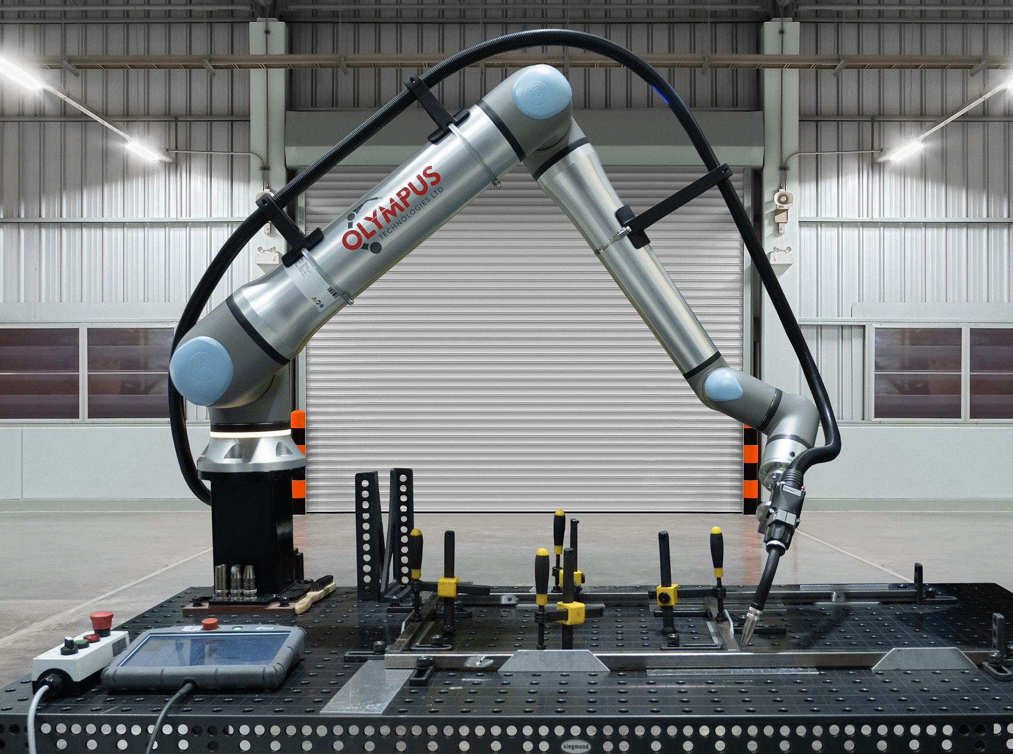














Choosing the right press brake tending cell is a process of matching your specific parts and press brake to the correct robot capabilities. The core decision balances payload capacity, functional reach, and end-of-arm tooling against your production needs. A typical successful system, like one we build around a Universal Robots UR20, can achieve a sub-16-month ROI by running lights-out on previously operator-dependent jobs.
Our integration process systematically addresses these variables to de-risk the investment. A turnkey cell from Olympus Technologies typically costs between £55,000 and £95,000, depending heavily on the factors below.
Key selection factors
Payload is the first calculation we perform, and it is non-negotiable. You must account for the maximum sheet weight plus the gripper weight, then add a safety factor of at least 20% for longevity and ISO compliance. A 15 kg blank handled by a 4 kg gripper needs a cobot with a payload greater than 19 kg, making a 20 kg class robot like the UR20 a minimum starting point.
Reach determines the maximum part size you can handle. The cobot must reach from the centre of the infeed stack to the press brake backgauge at its furthest point, which needs a reach of at least half the blank's diagonal plus any standoff distance. The UR20's 1750 mm reach accommodates most standard sheet sizes, but for exceptionally large parts a linear track may be required.
The press brake's controller dictates the integration method. Modern controllers like Delem or Cybelec offer direct communication protocols, letting the cobot and press handshake through each bend step. Older machines require I/O integration, where we wire into the press's cycle-start and safety circuits to create a less sophisticated but equally reliable system.
End-of-arm tooling is the final critical hardware choice. We typically specify magnetic grippers for ferrous materials due to their reliability with oily or perforated sheets. For aluminium or stainless steel, vacuum grippers are necessary, though they require careful consideration of surface quality and porosity.
Example cell configurations
To illustrate these trade-offs, here are two common configurations our engineers specify for UK fabrication shops. The choice depends entirely on the parts you produce today and the parts you anticipate producing in future.
| Attribute | Config A: light-duty / non-ferrous | Config B: heavy-duty / ferrous |
|---|---|---|
| Cobot model | Universal Robots UR10e | Universal Robots UR20 |
| Payload (nominal) | 12.5 kg | 20 kg |
| Reach (nominal) | 1300 mm | 1750 mm |
| Gripper type | Vacuum (e.g. Schmalz FXCB) | Magnetic (custom array or standard) |
| Typical part | 2 mm aluminium sheet, under 8 kg | 5 mm mild steel blank, under 15 kg |
| Brake integration | Direct (e.g. Delem DA-Touch) | I/O-based (for older machines) |
| Indicative cost | £55,000 to £70,000 | £70,000 to £95,000 |
Data based on typical Olympus Technologies project specifications and current 2024 pricing. Costs include the robot, gripper, safety system, integration, and commissioning.
What changes the answer?
The specifications above are common starting points, but the optimal configuration changes when part complexity or material properties shift. A standard setup for mild steel will not work for stainless steel without adjustments. These nuances are where off-the-shelf solutions fail and application-specific engineering becomes essential. We often see clients who have been quoted for a standard cell that fails to account for one critical variable, which leads to poor performance or the inability to run certain jobs.
How does material finish impact gripper choice?
Your material's finish and composition directly constrain your gripper options. Magnetic grippers are our default for mild steel because they are unaffected by cutting oils, surface dust, or perforations that cause vacuum cups to lose suction, making them highly reliable for raw blanks. Once you introduce non-ferrous materials like aluminium or stainless steel, magnetic grippers are useless and we switch to vacuum, which brings new constraints. Polished or brushed stainless can be too smooth for some cups, while the slight oil film on Zintec can compromise grip over a long shift. For these we specify high-friction cups and multi-stage vacuum generators to guarantee a secure lift.
What if parts require flipping between bends?
Many complex parts require flipping to form flanges on opposite sides, and this single requirement fundamentally changes cell layout and programming. A simple pick-and-place cell cannot do this without extra hardware. It forces a choice: either a dual-gripper setup on the arm or a dedicated re-gripping station. The dual gripper is faster but adds weight and complexity to the EOAT, potentially reducing net payload. A fixed re-gripping or flipping table is more robust and allows heavier parts, but adds a step to the cycle and increases time per part. We model both scenarios to find the best balance of throughput and cost for your specific parts.
Related resources
- Gripper technology: Vacuum vs Mechanical Grippers for Cobots.
- Ferrous handling: Magnetic Grippers for Cobot Machine Tending.
- Financials: Press Brake Cobot ROI for Low-Mix, Low-Volume.
- Cost breakdown: Press Brake Tending Cost UK.
Frequently asked questions
What is the most common mistake when specifying a press brake cobot?
Under-specifying payload and reach. Engineers often calculate using only the part weight, forgetting the gripper's mass, or measure reach to the press bed but not to the furthest backgauge position, leading to a robot that cannot complete all bend sequences.
How long does commissioning take?
For a standard turnkey cell, physical installation takes 2 to 3 days. Full commissioning, including programming the first batch of parts, safety validation, and operator training, typically takes an additional 3 to 5 days on-site.
Can one cobot tend multiple press brakes?
Yes, and it is a common request for improving asset utilisation. The most effective method is mounting the cobot on a linear 7th-axis rail positioned between two presses. This adds significant cost (£15k to £25k) and complexity but can deliver a strong ROI if both machines have high uptime requirements.
How does the cobot know where the blank is?
Most cells use physical fences or trays to create a repeatable pickup point for stacked blanks. For higher precision or randomly placed parts, we integrate a 2D vision system; the camera identifies the blank's position and orientation and sends coordinates to the cobot for a precise pickup.
Next steps
Specifying a press brake cell involves balancing dozens of variables. The most effective way to guarantee performance is to work with an integrator experienced with your specific parts and machinery.
Our process starts with a no-obligation consultation to analyse your parts and production goals. We can provide a detailed proposal with a firm price, projected ROI, and a clear timeline. Contact our engineering team today to book a site visit or a virtual demonstration.