













A cobot must carry the combined mass of the part, EOAT and dynamic allowance while reaching every work point without exceeding centre of gravity, duty cycle or thermal limits. Typical Universal Robots model bands cover payloads from 3 kg to 30 kg and reaches from approximately 500 mm to 1,300 mm.
Start with the process requirements
Cobot sizing starts with a defined process rather than a preferred robot model. Record the part mass, EOAT mass, cable package mass, required cycle time, operating hours, mounting position and coordinates of every process point.
The robot datasheet states a maximum payload and reach, but these values do not guarantee process performance at every pose. Payload capacity changes with centre of gravity, acceleration, joint position and wrist orientation.
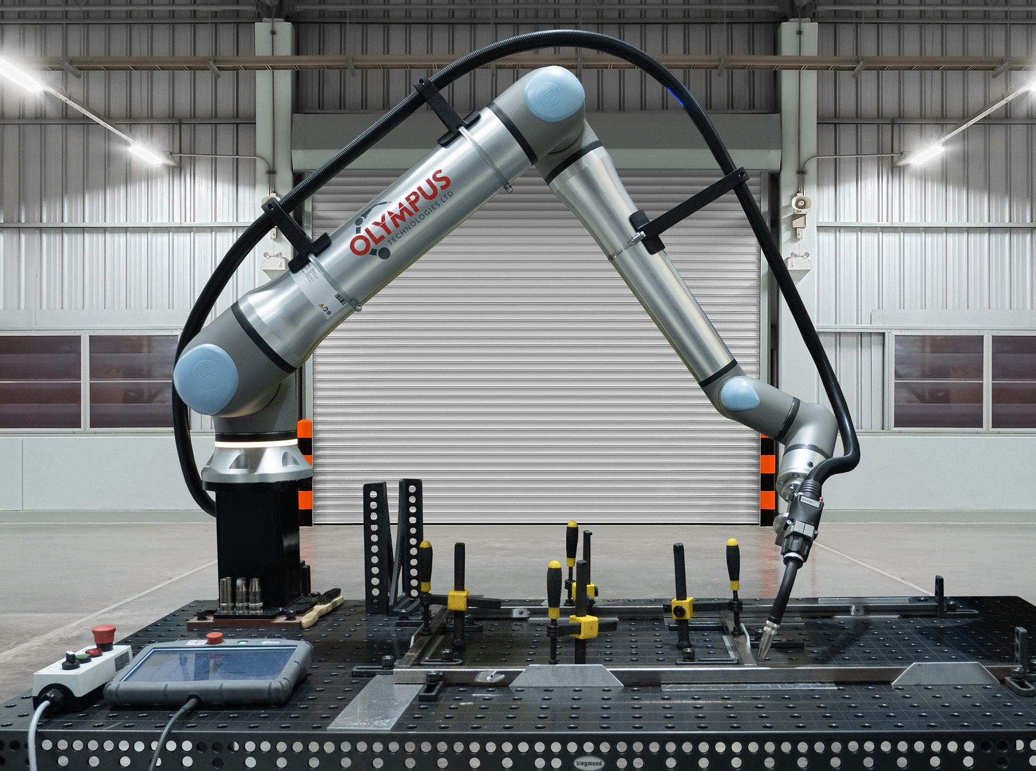
For welding, document torch angle, stick-out, joint access, seam length and reorientation moves. A cobot welding cell also requires space for the power source, wire feed, fume extraction and operator access.
Calculate total payload
Use the following sizing equation:Total design payload = part mass + EOAT mass + wrist-mounted accessories + dynamic allowance
The EOAT figure includes the tool, adaptor plate, fasteners, sensors, valves and any cable support attached beyond the wrist. Welding applications include the torch, torch bracket, collision sensor, neck, contact tip and the moving portion of the cable package.
Apply a documented dynamic allowance rather than selecting a robot at its static payload limit. A starting allowance of 10% to 20% suits controlled handling or welding motions, while high acceleration, abrupt direction changes and large offsets require calculation against the manufacturer's load diagrams.
A 10 kg cobot carrying a 9.8 kg assembly has only 0.2 kg of nominal capacity remaining. That margin does not account for tooling changes, cable drag, manufacturing tolerances or future process adjustments.
Check centre of gravity and wrist torque
Payload mass alone does not define an acceptable load. The load's centre of gravity creates torque around the robot wrist, and torque increases as the offset from the mounting flange grows.
Calculate static moment using:Moment in Nm = load mass in kg × 9.81 × centre of gravity offset in metres
An 8 kg tool with its centre of gravity 0.20 m from the flange creates a static moment of 15.7 Nm. Acceleration adds dynamic torque, so confirm the complete load case against the manufacturer's centre of gravity envelope and permitted wrist moments.
Long grippers, offset brackets and special torch necks move the centre of gravity away from the flange. Reducing adaptor thickness or rotating the tool can bring the load inside the permitted envelope without increasing nominal payload.
Measure working reach correctly
Required reach is measured from the robot's mounting reference to the furthest process point, then adjusted for tool geometry and the approach orientation. Do not treat the tool centre point as if it were located at the wrist flange.
Map the nearest, furthest, highest and lowest tool centre point coordinates in the proposed installation. Add the torch, gripper or spindle offset in the orientation used at each point.
A robot with 1,300 mm maximum reach does not provide a 1,300 mm usable spherical workspace. Joint limits, wrist alignment, singularities, fixtures and cable routing remove usable positions from the nominal envelope.
Offline simulation or a physical reach study verifies every process pose and transition. The study must include loading positions, tool-change positions, maintenance access and safe recovery poses.
Match payload and reach bands
The table provides planning bands for current and recent Universal Robots families. Confirm exact specifications, centre of gravity limits and availability against the selected model's current technical manual.
| Nominal payload band | Approximate reach band | Typical process fit | Main sizing check |
|---|---|---|---|
| 3 kg | 500 mm | Inspection, light assembly, compact benchtop tasks | Short reach and small EOAT |
| 5 kg | 850 mm | Light handling, testing, screwdriving | Tool mass and local access |
| 10 kg to 12.5 kg | 1,300 mm | Welding, machine tending, medium handling | Wrist moment and cycle time |
| 16 kg to 20 kg | 900 mm to 1,300 mm | Heavier tooling, loaded grippers, machine tending | Mount stiffness and dynamic load |
| 25 kg to 30 kg | 1,300 mm | Heavy parts, dual grippers, larger EOAT | Guarding, stopping distance and floor loading |
Selecting extra reach without checking payload creates a weak design. Selecting extra payload without checking geometry leaves unreachable seams or machine positions.
Account for duty cycle and thermal derating
Duty cycle describes the proportion of scheduled time during which the robot performs loaded motion. A process running for 45 seconds in each 60-second cycle has a 75% process duty cycle before planned breaks and stoppages.
High duty cycle raises motor, gearbox and controller temperatures. High ambient temperature, repeated maximum acceleration, large joint torque and restricted controller ventilation reduce thermal margin.
Review the manufacturer's permitted ambient range, continuous operation guidance and thermal protection behaviour. Test the final programme for a production-representative period with the intended payload, acceleration, dwell time and cable routing.
Welding introduces additional thermal loads near the wrist through radiant heat, spatter and hot fixtures. Correctly selected cobot welding covers protect surfaces from contamination, but covers must not restrict joint movement or trap prohibited heat around components.
Compare mounting arrangements
Floor mounting gives a rigid reference and suits cells where the robot remains beside one fixture. The base plate, anchors and concrete must resist the manufacturer's stated static and dynamic loads.
A pedestal raises the robot above fixture obstructions and shifts the useful workspace towards the process. Pedestal height and orientation often allow a shorter-reach model to access the same work envelope with better joint posture.
Wall or inverted mounting changes gravity loading and cable behaviour. Use only orientations approved for the selected model and enter the mounting orientation correctly in the controller configuration.
A linear rail adds travel rather than arm reach. Rail systems require position repeatability, cable management, guarding, additional risk assessment and coordination between rail and robot controls.
Work through a welding torch example
Consider a welding application with a 3.2 kg torch package, a 0.8 kg adaptor and collision sensor, and 0.5 kg of wrist-supported cable hardware. The wrist-mounted mass totals 4.5 kg.
Applying a 15% dynamic allowance gives 4.5 × 1.15 = 5.18 kg. A 5 kg-rated cobot fails the design payload, while a 10 kg to 12.5 kg model provides nominal payload margin subject to the load diagram.
The package centre of gravity sits 180 mm from the flange. Its static moment is 4.5 × 9.81 × 0.18 = 7.95 Nm, excluding dynamic torque and cable forces.
The furthest seam point lies 1,050 mm from the proposed base axis, and the torch tool centre point extends 180 mm beyond the flange. A reach study must therefore validate the required wrist position, torch angle and joint posture rather than adding both dimensions blindly.
For an 80% scheduled duty cycle, validate the programme under representative welding motion and ambient conditions. Torch routing and the Dinse connector arrangement must prevent drag from altering the load or restricting wrist rotation.
Use a final selection gate
Approve the robot only when payload, centre of gravity, wrist moment, reach, joint posture, cycle time and duty cycle all pass. Record each result in the integration design file.
Complete the machinery risk assessment for the full application rather than the bare cobot. PUWER duties, UKCA or CE marking, stopping performance, fixtures, EOAT and process hazards determine whether collaborative operation is valid.
From robot specification to cell design
Cobot sizing defines the mechanical boundary of the integration, but the complete cell determines production performance. Fixtures, guarding, sensors, process equipment and operator tasks alter access, stopping distance and cycle time.
A robot marketed as collaborative does not make welding or handling intrinsically safe. Sharp EOAT, hot workpieces, arc radiation, fumes, trapped spaces and impact energy remain application hazards under the machinery risk assessment.
The production target also sets a practical sizing boundary. A robot that reaches every point can still miss takt time when conservative acceleration, long clearance moves or repeated reorientation extend the cycle.
Compare the simulated cycle with measured manual work and the required output per shift. For loading applications, the cobot versus manual loading comparison helps separate labour utilisation from pure robot cycle time.
Integration choices then refine the model selection. A lighter EOAT reduces payload and wrist torque, a pedestal improves workspace utilisation, and a rail serves multiple stations at the cost of control and guarding complexity.
Freeze the robot model only after completing process mapping, load calculations, reach simulation and a preliminary risk assessment. This order prevents the robot specification from constraining the fixture and safety concept before the process has been verified.
Payload and reach selection checklist
Use this sequence before requesting a quotation:
1. Weigh the part, EOAT, adaptor, fasteners, sensors and wrist-supported services.
2. Define a dynamic allowance from acceleration, direction changes and process forces.
3. Locate the three-dimensional centre of gravity for every tool and part state.
4. Check wrist moments and centre of gravity limits against the technical manual.
5. Map all tool centre point coordinates and required orientations.
6. Simulate joint limits, singularities, fixture collisions and cable routing.
7. Calculate process duty cycle from loaded motion and total scheduled cycle time.
8. Validate temperature, acceleration and cycle time under production conditions.
9. Select floor, pedestal, wall, inverted or rail mounting from the verified workspace.
10. Complete the application risk assessment and conformity route.
For welding projects, assess operational readiness before detailed engineering using the five signs for a cobot welding cell.
Related tooling decisions
EOAT selection directly affects payload, centre of gravity and achievable acceleration. Vacuum tooling often reduces mechanism mass, while mechanical grippers provide positive retention for defined part geometries.
Compare these options through the vacuum versus mechanical gripper guide. Use measured part mass, surface condition, required grip force and loss-of-power behaviour as selection inputs.
Frequently asked questions
Can a cobot run continuously at its maximum payload?
The nominal payload does not guarantee unlimited operation at maximum acceleration or in every pose. Continuous suitability depends on centre of gravity, joint torque, motion profile, ambient temperature and the manufacturer's thermal limits.
Is maximum reach the same as usable reach?
No. Maximum reach describes a geometric boundary, while usable reach depends on tool orientation, joint limits, singularities, fixtures and collision clearance.
How much payload margin is appropriate?
A 10% to 20% dynamic allowance provides an initial planning range for controlled handling and welding. Final approval requires the manufacturer's load diagrams, wrist moment limits and the programmed acceleration profile.
Does the robot carry the welding workpiece?
Most cobot welding configurations hold the torch while the fixture supports the workpiece. Positioners add coordinated axes and change cell geometry, controls, risk assessment and cycle time.
Does a longer torch neck increase reach?
A longer neck moves the tool centre point farther from the flange, but it also increases centre of gravity offset and wrist moment. The resulting geometry requires load and collision checks at every welding orientation.
When is a linear rail preferable to a longer arm?
A rail suits long fixtures, multiple machines or separated workstations where one fixed base cannot cover the required area. Its specification must include travel speed, repeatability, dynamic loading, cable management and safeguarding.
Does a larger cobot always provide a faster cycle?
No. Cycle time depends on permitted acceleration, travel distance, payload, safety limits and process dwell. A larger model can add inertia and stopping distance without improving the constrained process step.