













A cobot is not automatically safe: UK compliance applies to the complete application, including the robot, EOAT, workpiece, process, controls and surrounding equipment. BS EN ISO 10218, ISO/TS 15066, PUWER and machinery product law provide the principal framework for assessing that application.
What is a collaborative robot application?
A collaborative robot application is an industrial robot system designed for people and robots to share a defined collaborative workspace under specified controls. Collaboration describes the operating arrangement, not an unrestricted property of the robot.
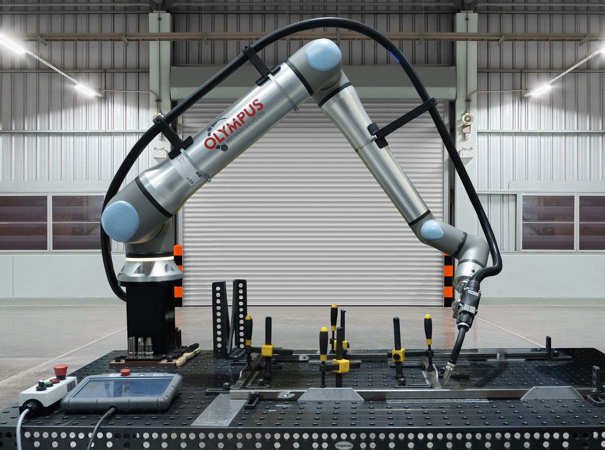
A force-limited arm fitted with a sharp gripper can still create puncture, crushing and trapping hazards. A welding torch adds heat, electrical, arc radiation, fume, spatter and fire hazards that the robot's joint safety functions do not control.
The system boundary includes the robot arm, controller, teach pendant, EOAT, fixtures, workpiece, software, safety devices and interfaces with other machinery. The integrator assesses the foreseeable interactions between those elements across production, setup, cleaning, fault recovery and maintenance.
Which standards govern UK cobot safety?
BS EN ISO 10218-1 addresses safety requirements for industrial robot manufacturers. BS EN ISO 10218-2 addresses the integration, commissioning, operation and maintenance of industrial robot applications and robot cells.
ISO/TS 15066 supplements ISO 10218 with guidance for collaborative operation. It provides technical information for workspace design, contact assessment and power and force limiting.
A standard is not a substitute for a risk assessment. Its requirements and test methods provide evidence that identified risks have been reduced through engineering controls and validated safety functions.
| Document or duty | Primary scope | Practical relevance |
|---|---|---|
| BS EN ISO 10218-1 | Industrial robot design | Robot safety functions and manufacturer requirements |
| BS EN ISO 10218-2 | Robot application integration | Cell layout, safeguarding, commissioning and validation |
| ISO/TS 15066 | Collaborative operation | Contact limits, body regions and collaborative workspace guidance |
| PUWER 1998 | Use of work equipment | Suitability, guarding, maintenance, inspection and training |
| Machinery product law | Supply of machinery | Conformity assessment, technical documentation and marking |
What are the four collaborative operating modes?
ISO 10218 and ISO/TS 15066 describe four collaborative operating modes. A cell can use 1 mode or combine several modes when the risk assessment defines clear transitions and validates each safety function.
Safety-rated monitored stop
The robot stops before a person enters the collaborative workspace and remains stopped while the person is present. Drives can remain powered when the safety architecture maintains the monitored stop and prevents hazardous motion.
Production resumes only after the defined clearance and restart conditions are satisfied. This mode suits loading, inspection or intervention tasks where simultaneous human and robot motion is unnecessary.
Hand guiding
The operator directs robot motion through a hand-guiding device positioned near the EOAT or another suitable control point. The system uses an enabling function, emergency stop provision and safety-rated speed monitoring defined by the application design.
Hand guiding is distinct from manually pushing a standard cobot arm during programming. Hazards from the EOAT, workpiece and nearby structures remain part of the assessment.
Speed and separation monitoring
The robot and person move simultaneously while the safety system monitors their separation. Robot speed reduces as the person approaches, and protective stopping occurs before the separation distance becomes unsafe.
The protective separation distance depends on human approach speed, robot stopping time, sensing-system response and position uncertainty. A laser scanner, safety camera or equivalent safety-rated device supplies the required detection data.
Power and force limiting
Power and force limiting permits contact only where contact forces, pressures and energies stay within the validated limits for the relevant body region. The assessment covers both transient contact, where the person can recoil, and quasi-static contact, where a body part becomes trapped.
Robot torque sensing alone does not validate the application. Testing covers the selected speed, payload, EOAT geometry, workpiece, contact point and potential trapping condition.
How does ISO/TS 15066 address contact limits?
ISO/TS 15066 provides biomechanical reference values for pain onset across defined body regions. Integrators use those values as part of power and force limiting assessment rather than as universal robot speed limits.
Contact pressure depends on force and the contact area. A narrow tool edge produces higher pressure than a broad rounded surface under the same measured force.
Quasi-static contact presents greater crushing risk because the person can become pinned between the moving system and a fixed object. Cell layouts reduce these trapping points before control settings are used as a secondary measure.
Validation uses calibrated measurement equipment and a test configuration that represents the relevant body-region stiffness. The resulting report records peak force, pressure where assessed, robot settings, payload, test location and acceptance criteria.
What does PUWER require from a cobot user?
The Provision and Use of Work Equipment Regulations 1998 require employers to provide work equipment that is suitable, maintained and used by trained personnel. PUWER also requires effective controls, isolation, protection against specified hazards and safeguards for dangerous parts.
A conformity mark does not discharge the employer's PUWER duties. The user retains responsibility for the equipment in its installed environment and for changes made after commissioning.
Inspection intervals follow deterioration risk, usage, manufacturer instructions and site conditions. Records support evidence that safety devices, emergency stops, interlocks and protective stops continue to function as validated.
Operator instruction covers normal production, teaching, reset, jam clearance and foreseeable faults. Access to safety settings is restricted to authorised personnel.
How do UKCA and CE marking apply?
Machinery placed on the Great Britain market follows the applicable UK machinery product regime and accepted marking arrangements in force on its placement date. Northern Ireland follows separate rules linked to EU product legislation, including CE marking and UKNI requirements in specified cases.
The complete robot application often constitutes an assembly of machinery. The responsible manufacturer or integrator completes the conformity assessment, compiles the technical file, provides instructions and issues the relevant declaration before supply or first use.
An incorporated robot can carry its own marking and documentation without making the finished cell compliant. Changes to EOAT, fixtures, safety logic or process equipment trigger review because they alter the assessed system.
Why is risk assessment the controlling process?
The risk assessment determines whether collaboration is appropriate and which protective measures are required. It starts with limits of machinery and covers intended use, reasonably foreseeable misuse and every lifecycle phase.
Hazards are identified before risk is estimated from severity and probability. Risk reduction then follows the hierarchy of inherently safe design, safeguarding and complementary protective measures, followed by information for use.
Validation confirms that safety-related control functions achieve their specified performance and stopping behaviour. The final evidence includes drawings, safety requirement specifications, calculations, test results, declarations, manuals and residual-risk information.
A production change requires reassessment when it alters payload, reach, cycle time, tool geometry, workpiece, fixture, speed, software or access. The same rule applies when a new URCap affects motion, commands or safety-related behaviour.
From general cobot compliance to welding-cell protection
The standards framework establishes how collaborative motion, access and contact risks are controlled. Welding introduces process hazards that sit outside the arm's power and force limiting functions.
Arc welding exposes personnel to ultraviolet and infrared radiation, visible glare, hot metal, spatter, fume and ignition sources. The welding power source, torch, wire feed, work return, gas supply and extraction system expand the application boundary beyond the cobot controller.
The risk assessment determines whether the welding process remains collaborative during arc-on operation. A safety-rated monitored stop, speed and separation monitoring, fixed guarding or an enclosed process zone often controls access while the arc is active.
Welding covers form a guarding layer when their material, coverage and fixing method match the identified exposure. They do not replace extraction, electrical protection, fire controls, interlocks or validated robot safety functions.
A cover must also avoid creating new hazards through restricted robot reach, snagging, concealed damage or interference with emergency access. Its installation is assessed across the robot's complete programmed envelope and foreseeable recovery movements.
For a detailed treatment of material selection and coverage, see cobot welding covers.
Safety glossary for cobot projects
| Term | Definition |
|---|---|
| Collaborative workspace | The defined space where the robot system and a person can perform tasks concurrently under specified controls |
| EOAT | End-of-arm tooling, including grippers, torches, sensors and tool changers attached to the robot flange |
| Protective stop | A controlled stop initiated for safety purposes while control-system monitoring remains active |
| Safety-rated function | A control function designed and validated to achieve a specified risk reduction |
| Transient contact | Contact where the person is not trapped and can move away from the robot system |
| Quasi-static contact | Contact where a body part is clamped between the robot system and another surface |
| Validation | Evidence-based confirmation that protective measures and safety functions meet their specifications |
| Residual risk | Risk remaining after the specified risk-reduction measures have been applied |
Welding cover selection within the safety assessment
A welding cover is selected against arc-radiation resistance, flame behaviour, spatter exposure, viewing requirements and cell geometry. The assessment also records attachment points, inspection criteria and replacement conditions.
Flexible covers suit layouts where operators require controlled access and the cover remains outside the robot envelope. Hard guarding suits higher-energy processes, frequent spatter or layouts requiring stronger physical separation.
Cover dimensions follow the source position and every credible line of sight to occupied areas. Guidance on sizing and material factors is available in how to choose a cobot welding cover.
Frequently asked questions
Is a cobot safe without guarding?
No. Guarding requirements depend on the complete application risk assessment rather than the robot label.
A low-speed, rounded handling task can pass power and force limiting validation without perimeter fencing. A sharp workpiece, welding arc or trapping point requires additional risk reduction even when the robot has certified safety functions.
Does ISO/TS 15066 certify a cobot cell?
No. ISO/TS 15066 provides collaborative-operation guidance and biomechanical reference data.
The responsible organisation assesses conformity for the complete application under the applicable legal framework. Validation records demonstrate that the selected measures achieve the required risk reduction.
Can one safe speed be used for every cobot task?
No. Safe motion depends on payload, EOAT, geometry, contact location, separation distance and stopping performance.
Changing a gripper or workpiece changes inertia and contact characteristics. The revised setup requires review and testing against the safety specification.
Who signs off a cobot installation?
The party placing the complete machinery assembly on the market or putting it into service holds the relevant conformity responsibilities. The employer separately retains PUWER duties for use, maintenance, inspection and training.
Responsibilities are recorded in the project scope before design begins. Documentation identifies who produces the technical file, declaration, instructions, validation report and site risk assessment.
Does a welding cover make arc-on collaboration safe?
No. A welding cover controls specified radiation and spatter exposure only when its material and coverage are suitable.
Arc-on collaboration also requires controls for fume, heat, electricity, fire, robot motion and access. An overview of the complete process is available on the cobot welding page.