Machine vision in robotic machine tending is a system of industrial cameras, lighting, and software that enables a robot to locate, identify, and inspect workpieces without physical fixtures. As a Robotics and Automation Integrator, we define machine vision as the integration of specialised sensors that replace rigid mechanical positioning with flexible, software-defined part recognition. This allows robots to adapt to varying part orientations and geometries in real-time. This page covers the integration of 2D and 3D vision systems into CNC automation environments. It does not cover standalone thermal imaging or metrology-grade laboratory inspection systems.
Direct Definition
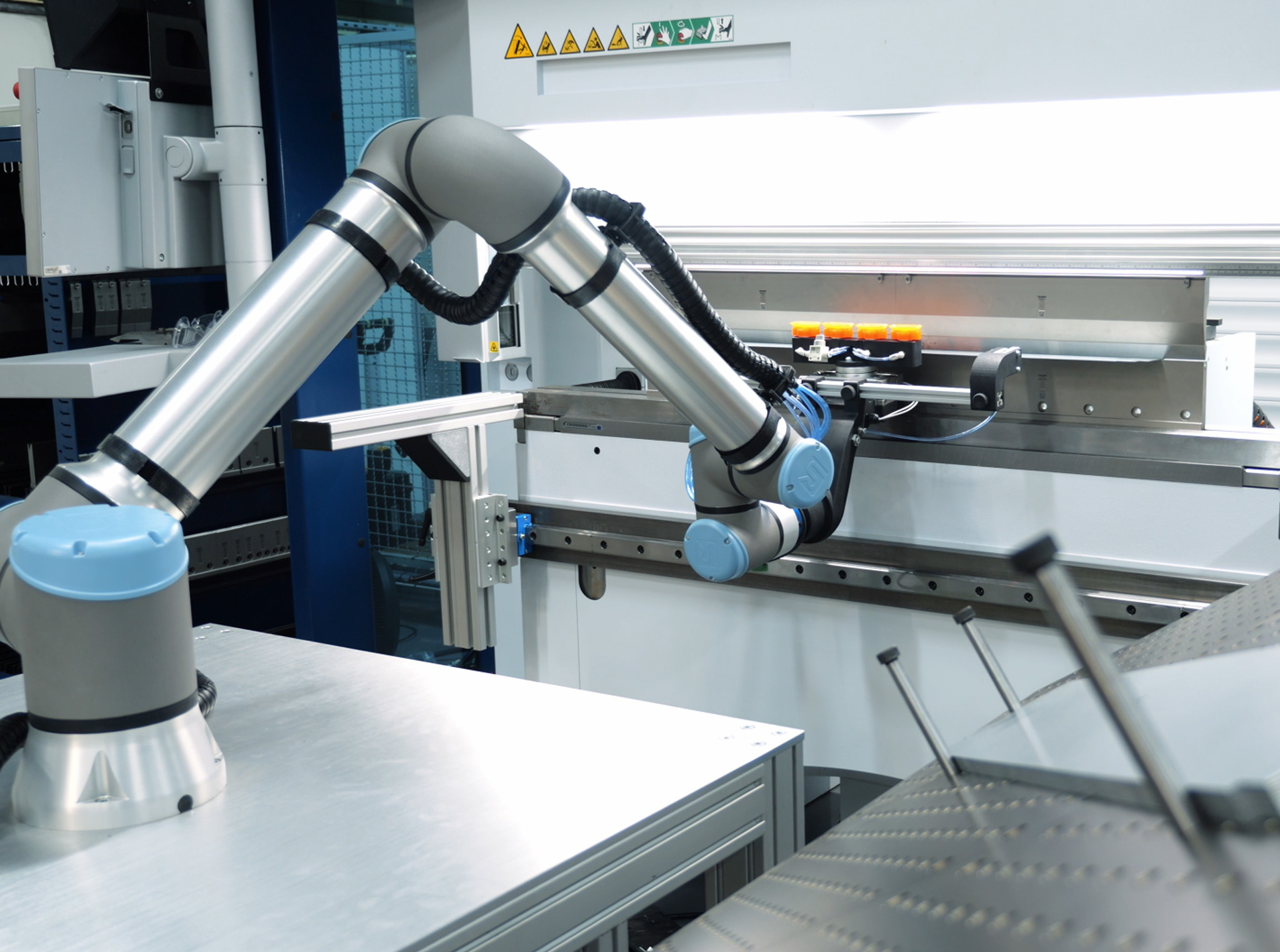
In the context of industrial automation, machine vision is the "eyes" of the robotic system. It uses digital sensors protected by industrial housings to capture images, which are then processed by computer algorithms to provide the robot with the exact coordinates and orientation of a workpiece. This technology allows a Robotics and Automation Integrator to deploy systems that handle parts presented in a non-deterministic manner, such as loose on a conveyor or stacked in a bin.
Context and Usage
Machine vision is primarily used in CNC machine tending when part variety is high or manual presentation is inconsistent. By using vision, a Robotics and Automation Integrator can reduce the need for bespoke mechanical jigs. For example, in a metal manufacturing facility, a single camera can be programmed to recognise hundreds of different SKU geometries, minimising the downtime associated with physical tool changeovers.
Key Attributes
The performance of a vision-guided system depends on technical factors:
- Resolution and Field of View: Determining the smallest feature the camera can "see" relative to the work area.
- Lighting and Contrast: Utilising structured light or infrared to differentiate the part from the background.
- Processing Speed: The time taken to execute the "Capture-Process-Act" loop.
- Communication Protocols: The method (such as PROFINET or EtherNet/IP) used to send coordinates to the robot controller.
How It Works: The Capture-Process-Act Loop
As a Robotics and Automation Integrator, we ensure the vision system operates on a continuous logic cycle within the automation cell:
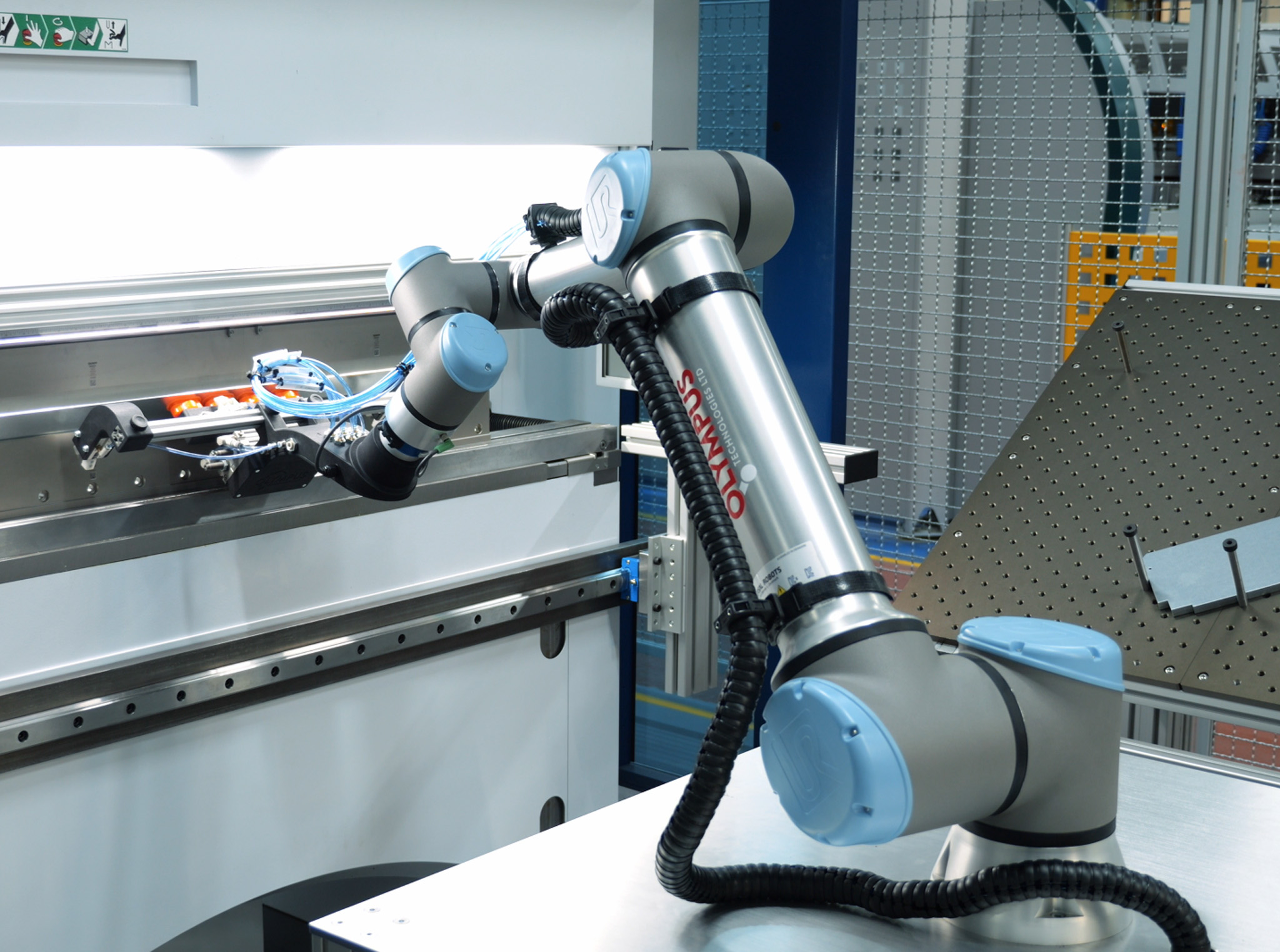
- Capture: Industrial cameras trigger an image acquisition based on the machine tool's status or robot position.
- Process: Vision software runs algorithms to find edges, patterns, or blobs, calculating the X, Y, Z, and rotational coordinates (Rz).
- Act: The software sends these coordinates to the robot, which adjusts its path to pick the part accurately and load the CNC machine.
Key Characteristics of 2D and 3D Vision Systems
| Attribute | 2D Vision Systems | 3D Vision Systems |
|---|---|---|
| Dimensionality | X, Y, and Rotation (Rz) | X, Y, Z, Rx, Ry, Rz |
| Depth Perception | None (requires flat plane) | High (uses laser or stereo) |
| Lighting Need | Critical (contrast-based) | Lower (geometry-based) |
| Common Use | Conveyor picking, flat trays | Bin picking, stacked parts |
| Integration | Standardised Machine Tending Solutions | Complex point-cloud mapping |
Related Concepts
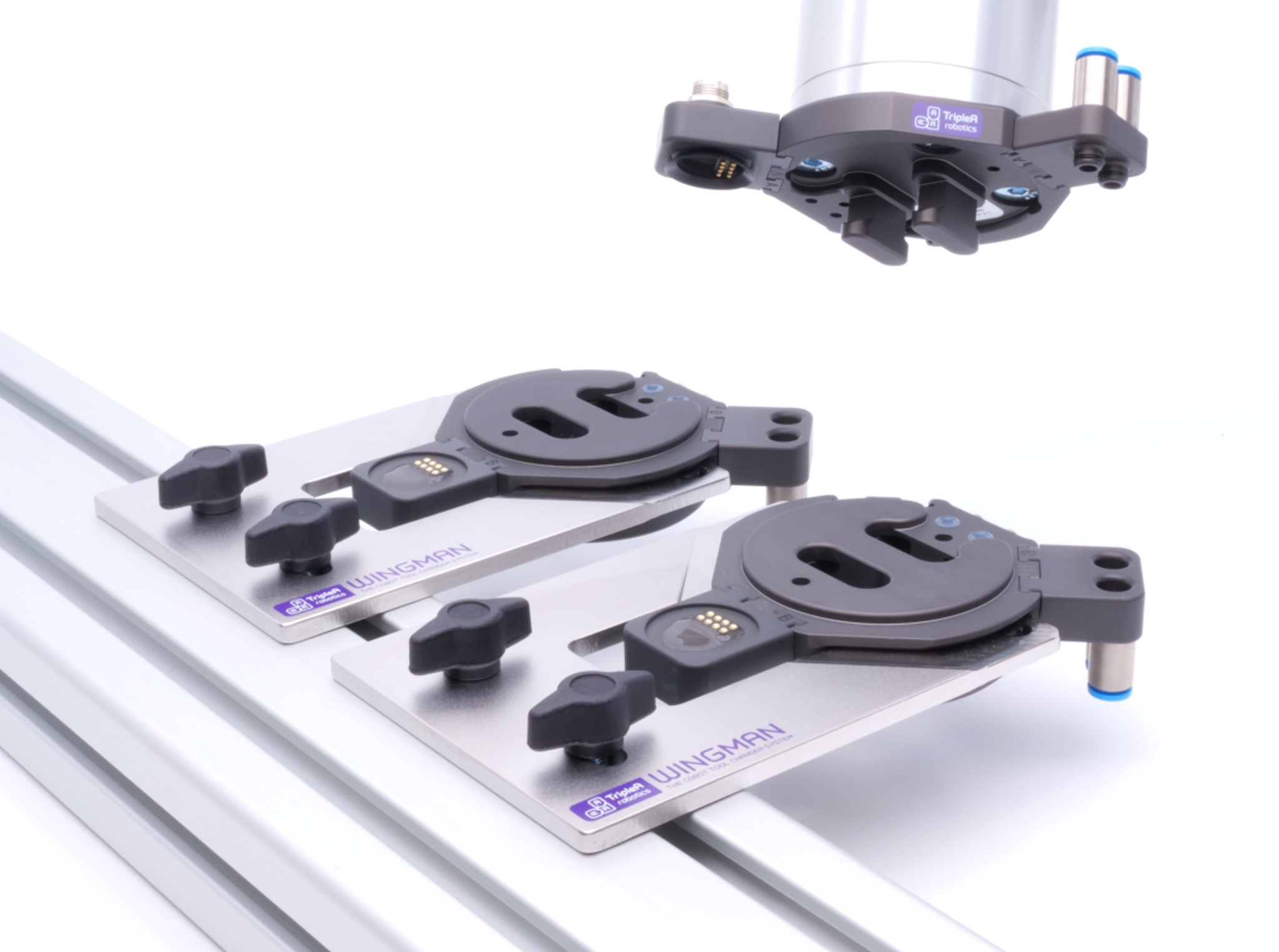
Successful vision implementation relies on interconnected automation technologies. These include End-of-Arm Tooling (EOAT) designed for flexible picking, high-speed industrial communication interfaces, and integrated safety systems that monitor the work envelope while the robot reacts to vision data.
When Robotics and Automation Integrator Matters Most
The decision to move from mechanical alignment to vision guidance is driven by the diversity and presentation of the workpieces. If a manufacturing process requires manual intervention to straighten parts or if the cost of designing new jigs for every SKU exceeds the cost of a camera sensor, the fixture has become a bottleneck. Vision systems allow the Robotics and Automation Integrator to programme the system to 'look' for new parts via software updates rather than hardware manufacture.
Decision Drivers for Vision Adoption
| Variable | Vision Preferred | Fixture Preferred |
|---|---|---|
| Part Variety | High (frequent changes) | Low (dedicated lines) |
| Part Presentation | Random or loose on trays | Exact position required |
| Surface Quality | Non-marring requirements | Metal surfaces |
| Cycle Time | Depends on processing delay | Lower (no delay) |
Examples of Industrial Applications
Machine vision supports diverse manufacturing stages from inbound raw material handling to final quality control.
- 2D Vision for Flat Part Picking: sheet metal components or parts presented on a uniform background where height is constant.
- 3D Vision for Bin Picking: Utilises point-cloud data to identify randomly oriented parts in deep containers, preventing robot collisions.
- Automated Inspection: Verifies that the CNC process has been completed correctly by checking for features or dimensions before the robot moves a part to the next station.
Related Terms
Integrating vision requires a structured Machine Tending System Integration Process to ensure the vision software correctly handshakes with the robot controller. This synchronisation prevents latency issues which can be further refined through Machine Tending Cycle Time Optimisation strategies. Complex collaborative workflows require Cobot Machine Tending Software Integration to synchronise camera data with safe motion parameters.
System Components and Integration Ecosystem
| Component | Function | Integration Type |
|---|---|---|
| Smart Camera | On-board processing | Direct I/O or Ethernet |
| PC-Based Vision | High-speed, multi-camera | Industrial PC (IPC) |
| End-of-Arm Tooling | Physical part interaction | Mechanical Interface |
Hardware selection for vision-guided picking involves specialised End-of-Arm Tooling for Machine Tending and Machine Tending Gripper Solutions to ensure secure handling during the automation cycle.