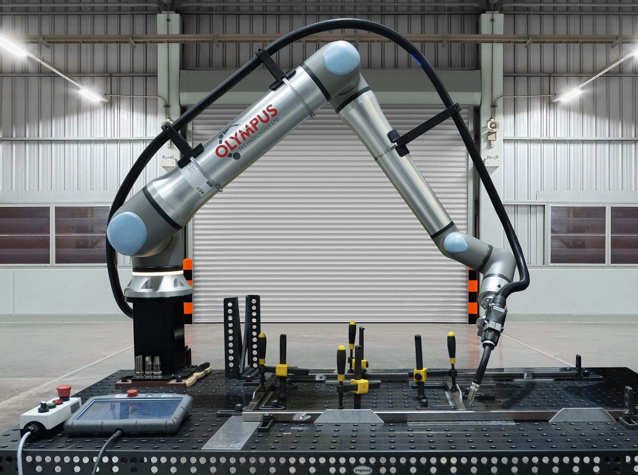















Pallet pattern software converts case, pallet and stacking data into robot positions, allowing a cobot to place every case without programming each coordinate manually. A palletising URCap provides this function inside the Universal Robots teach pendant interface.
What is pallet pattern software?
Pallet pattern software defines where each case sits on every pallet layer. It also controls the case orientation, layer sequence, pallet height and any intermediate operations.
The software generates a set of robot targets from product dimensions and stacking rules. The robot program then combines these targets with approach points, gripper actions and departure paths.
A palletising URCap is a software plug-in installed on a Universal Robots controller. It adds pallet creation, product setup and layer editing screens to the standard PolyScope interface.
The URCap does not remove the requirement for physical commissioning. An integrator still verifies EOAT clearance, payload, reach, cycle time, safety functions and the completed risk assessment.
What does a pallet pattern file contain?
A pattern file stores the geometric and process data required to build a repeatable pallet. File structures vary by software supplier, but the operational inputs remain consistent.
| Data field | Information stored | Operational purpose |
|---|---|---|
| Case dimensions | Length, width and height in millimetres | Calculates placement centres and clearances |
| Case mass | Gross mass in kilograms | Checks payload and pallet mass |
| Pallet dimensions | Length, width and usable height | Defines the stacking boundary |
| Layer map | Position and rotation of each case | Creates robot placement targets |
| Layer sequence | Order of layer designs | Controls interlocking and total height |
| Pattern type | Column, interlock or mixed | Sets the stacking structure |
| Slip sheets | Insertion layer and sheet dimensions | Adds sheet handling operations |
| Label orientation | Required outward-facing case side | Controls case rotation |
| Edge clearance | Distance from pallet perimeter | Prevents unacceptable overhang |
| Product gap | Spacing between adjacent cases | Allows dimensional and gripping tolerance |
Case dimensions must represent the packed product under production conditions. Carton bulge, tape seams and dimensional variation affect the clearance between neighbouring cases.
Label orientation is normally defined as 0, 90, 180 or 270 degrees relative to a pallet datum. This requirement can reduce cases per layer because not every geometric rotation remains acceptable.
Slip-sheet data adds pick and placement locations outside the standard case sequence. The cell also requires a sheet magazine, sheet-detection method and compatible vacuum EOAT.
Common pallet pattern types
The selected pattern determines load stability, case presentation and robot movements. Compression strength and transport conditions also influence the correct choice.
| Pattern type | Layer arrangement | Relative stability | Typical use |
|---|---|---|---|
| Column stack | Every layer repeats the same orientation | Lower lateral stability | Strong cartons, short pallets and display-ready loads |
| Full interlock | Alternate cases cross layer boundaries | High lateral stability | Distribution pallets exposed to handling and transport |
| Partial interlock | Selected rows rotate between layers | Medium to high stability | Cases requiring strength plus outward labels |
| Brick pattern | Cases overlap joints like brickwork | High stability | Uniform rectangular cartons |
| Pinwheel | Cases rotate around a central area | High rotational stability | Near-square cases and mixed orientation rules |
| Split or row pattern | Separate rows use different orientations | Medium stability | Rectangular cases with better deck utilisation in rows |
Column stacking aligns vertical carton edges, which preserves compressive strength. Its continuous vertical joints provide less resistance to sideways movement.
Interlocking breaks the vertical joints between layers. The rotated cases can reduce top-to-bottom carton strength when loads transfer through unsupported panel areas.
Generated patterns versus taught patterns
Generated patterns use an algorithm to calculate valid layer maps from case dimensions, pallet dimensions, gaps, overhang limits and orientation rules. The operator reviews the resulting options and selects a pattern that meets stability and presentation requirements.
Taught patterns record positions created through the teach pendant or a graphical layer editor. Each placement is entered individually or copied from an existing row, grid or layer.
Generated patterns reduce setup work when a site handles many case formats. They also provide consistent spacing because coordinates come from the same dimensional model.
Taught patterns provide direct control over unusual packs, asymmetric loads and customer-specific layouts. They take longer to create when every position requires manual definition and validation.
Both methods require a physical trial using production cartons. The trial confirms gripper access, case deformation, cumulative placement error and load stability.
Calculating utilisation on a 1200 x 1000 mm pallet
A standard 1200 x 1000 mm UK pallet has a deck area of 1,200,000 mm². Layer area utilisation equals the total footprint of cases in one layer divided by pallet deck area, multiplied by 100.
For a 400 x 300 mm case, each footprint occupies 120,000 mm². A simple orientation fits four cases along the 1200 mm side and two along the 1000 mm side, giving eight cases per layer.
The occupied case area is 8 × 120,000 = 960,000 mm². Layer area utilisation is 960,000 ÷ 1,200,000 × 100 = 80%.
Cube utilisation includes vertical space. For ten layers of 250 mm-high cases within a 2500 mm product stack, utilisation remains 80% because the cases use the full available height.
If the permitted product height is 2700 mm, the same load occupies 960,000 × 2500 = 2.4 m³ within a 1.2 × 1.0 × 2.7 = 3.24 m³ envelope. Cube utilisation is therefore 74.1%.
Higher utilisation does not automatically produce the safest load. Pattern approval also covers pallet edge support, carton strength, centre of gravity, transport restraint and label visibility.
How pattern changes affect changeover time
A saved and validated pattern can reduce recipe changeover to selecting the product code, confirming EOAT settings and loading the correct consumables. A barcode or production-system input can automate recipe selection where the control architecture supports it.
Changing case dimensions alters every calculated placement centre. It can also change cases per layer, layer count, robot reach, pallet height and the required lifting-column travel.
A label-orientation change can require a different layer map or an additional wrist rotation. The revised motion must remain inside joint limits and keep hoses clear of the load.
Adding slip sheets increases the number of robot actions per pallet. The resulting effect belongs in the complete palletising cycle-time calculation, including sheet pickup, detection and placement.
A previously commissioned recipe change commonly takes 1 to 5 minutes when only product selection and consumable checks apply. A new carton or unvalidated pattern requires offline preparation, physical trials and production approval, so it is an engineering change rather than a routine operator changeover.
Where pattern software sits within a palletising cell
Pattern software controls the placement recipe, but it does not control every constraint in the cell. The cobot, EOAT, conveyor, pallet station, guarding strategy and safety system determine whether the generated positions are physically executable.
Reach analysis confirms access to the lowest and highest placement points. A standard cobot base can become unsuitable when pallet height, deep rear corners or EOAT length place targets outside the working envelope.
Payload analysis includes the case, gripper, brackets, hoses and any retained vacuum components. The rated payload alone does not confirm performance because tool centre of gravity and wrist orientation also affect allowable loading.
Vacuum selection depends on case surface, porosity, mass and acceleration. The vacuum gripper selection process also defines cup arrangement and vacuum-loss detection.
Pattern execution forms one part of the wider cobot palletising solution. Commissioning links each recipe to conveyor stops, product detection, pallet presence, slip-sheet handling and completed-pallet release.
The integrated cell requires a risk assessment and PUWER compliance at the operating site. UKCA or CE marking obligations depend on the machinery supply arrangement and the applicable placing-on-the-market rules.
Pattern validation checklist
A new pattern requires validation before operators use it in production. The following checks connect the software model to the physical load:
1. Measure three production cases and record the largest external dimensions.
2. Confirm gross case mass at the highest permitted fill condition.
3. Check every placement for gripper access and adjacent-case clearance.
4. Verify pallet overhang and underhang against the customer specification.
5. Confirm labels face the specified pallet sides.
6. Build the complete layer sequence using production cartons.
7. Inspect vertical alignment, corner support and cumulative drift.
8. Test lift, transfer and transport restraint with the approved load.
9. Record the validated recipe revision and product code.
10. Restrict editing rights according to the site's change-control process.
The validation run also records cycle time and vacuum alarms. Case pickup failures often originate from porous board, tape position or inconsistent presentation rather than the layer map.
Software inputs that affect robot motion
Product gap changes more than visual spacing. A small gap reduces unused deck area but leaves less tolerance for carton bulge and placement error.
Approach height determines how far the EOAT travels above the existing load. Insufficient clearance creates collision risk, while excess clearance adds travel distance to every cycle.
Placement order affects wrist rotation and travel between targets. A shortest-path sequence can conflict with load stability when an unsupported case requires neighbouring cases first.
EOAT geometry sets the minimum clearance beside completed rows. Compare vacuum and mechanical tooling through the gripper selection guide before freezing layer layouts.
Related palletising decisions
Pattern software cannot compensate for an undersized robot or an unsuitable product presentation system. Robot selection starts with payload, reach, duty cycle, cycle time and environmental conditions in the palletising robot selection guide.
The financial case includes integration, guarding, conveyors, pallet handling, EOAT and commissioning. UK budget categories are set out in the 2026 cobot palletising cost guide.
Frequently asked questions
Can pallet software create mixed-case pallets?
Standard palletising URCaps generally focus on one case format per recipe. Mixed-case palletising requires order data, case identification, sequence planning and stability rules beyond a fixed repeating layer map.
Does a pattern file include robot speed?
Some packages store motion settings within the recipe, while others keep speed and acceleration in the main robot program. Commissioning documentation must identify which parameters change with the product code.
Can operators edit a layer from the teach pendant?
Most palletising URCaps provide graphical editing on the teach pendant. Access control and recipe revision records prevent unapproved production changes.
What happens when case height changes?
A height change alters layer elevations and total pallet height. The revised recipe requires checks for reach, lifting-column stroke, maximum load height and collision clearance.
Is the densest pattern always best?
No. The approved pattern balances deck utilisation with carton compression strength, lateral stability, gripping access, label orientation and transport requirements.